What is Comparator?
In Electronics, a comparator is used to compares two voltages (V) / Currents(I) and outputs a digital signal indicating which is larger than other. it consist of two analog input terminals and and one binary digital output . The output is ideally as follows
A comparator mainly has a specialized high gain Differential amplifier. Comparators are commonly used in devices that measure and digitize two analog signals, for example analog to digital signals (ADCs), as well as oscillators.
Verilog code for a 2 bit -comparator-VHDL
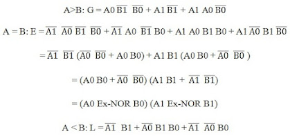
There are many different types of comparators. But, Here we have designed and implemented a simple 2bit-comparator which has two 2 bit inputs and three output bits these outputs says, whether one of the input is less ,greater or equal to the second input.
A 2-bit comparator is a device that compares 2-binary numbers, each of two bits and produces as one number is equal(=) or greater than (>) or less than (<) the other.
A simple 2-bit Comparator device is designed and implemented in VHDL/ Verilog Code.
The 2-bit comparator specifications are as follows:
Circuit Diagrams
This is the Verilog code for the 2bit-comparator:
 // Verilog code for 2-bit comparator
 module 2bit-comparator(input [1:0] A,B, output A-equal-B, A-less-B, A-greater-B);
 wire w0,w1,w2,w3,w4,w5,w6,w7;
 // A equal B output
 xnor x1(w0,A[1],B[1]);
 xnor x2(w1,A[0],B[0]);
 and x3(A-equal-B,w0,w1);
 // A < B output
 assign w2 = (~A[0])& (~A[1])& B[0];
 assign w3 = (~A[1])& B[1];
 assign w4 = (~A[0])& B[1]& B[0];
 assign A-less-B = w2 | w3 | w4;
 // A > B output
 assign w5 = (~B[0])& (~B[1])& A[0];
 assign w6 = (~B[1])& A[1];
 assign w7 = (~B[0])& A[1]& A[0];
 assign A-greater-B = w5 | w6 | w7;
 endmodule
 `timescale 10 ps/ 10 ps
 // Verilog test-bench code for 2-bit comparator
 module test_comparator;
 reg [1:0] A, B;
 wire A-less-B, A-equal-B, A-greater-B;
 integer i;
 comparator dutt(A,B,A-less-B, A-equal-B, A-greater-B);
 initial begin
      for (i=0;i<4;i=i+1)
      begin
           A = i;
           B = i + 1;
           #20;
      end
      for (i=0;i<4;i=i+1)
      begin
           A = i;
           B = i;
           #20;
      end
      for (i=0;i<4;i=i+1)
      begin
           A = i+1;
           B = i;
           #20;
      end
 end
 endmodule
2 bit comparator logic diagram,


No comments:
Post a Comment