script async='async' crossorigin='anonymous' src='https://pagead2.googlesyndication.com/pagead/js/adsbygoogle.js?client=ca-pub-6016566166623052'/> Verilog coding: 4-bit binary counter
Showing posts with label 4-bit binary counter. Show all posts

Sunday, 26 April 2020

Four-bit binary counter with parallel load


Graphical Symbol of Four-bit binary counter with parallel load

Four-bit binary counter with parallel load

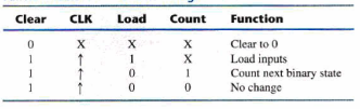
Functional Table of Four-bit binary counter with parallel load


fpga verilog code example
Verilog HDL of Four-bit binary counter with parallel load
module Bin-Counter-4bit-Par_Load (
output reg   [3: 0]  A-count,                    // Data output
output          C-out,                                  //Output any
input            [3: 0] Data-in,                      // Data input
input            Count,                                  //Active high to count
                      Load,                                   //Active high to load
                      CLK,                                   // Positive-edge sensitive
                      Clear                                   //Active low  
);
assign      C-out = Count & (~Load) & (A_count == 4'b111l);
always @ (posedge CLK, negedge Clear)
If (~Clear)                          A_count <= 4'b0000;
else If (Load)                      A_count <= data-in;
else If (Count)                    A_count  <= A_count + l'bl;
else                                     A_count <= A_count;            //redundant statement
endmodule


D-Latch Verilog code:

The D-latch is a transparent and responds to a change in data input with a change in output, as long as
the enable input is high. It has one output Q and  two inputs, D and en. Since Q is evaluated in a procedural statement, it must be declared as register type. D-latch responds to input signal levels, so the two inputs are listed without edge qualifiers in the event enable expression following the @ symbol in the always statement. it has only one blocking procedural assignment statement and it also specifies the transfer of D-input to Q-output if logic 1 i.e when enable is true. This statement is executed every time when there is a change in input D if enable is  logic1.
D-Latch Gate level and truth Table.
D-Latch Graphical Symbol.
fpga verilog code example
Verilog of D latch

module D-latch (Q, 0, en); // en is enable
output Q;
Input D, en;
reg Q;
always @ (en or D)
If (en) Q <= D;   //Same as: If (enable == 1)
endmodule


// Alternative syntax 
module D-latch (output reg Q, input enable, D);
always @ (enable, D)
If (enable) Q <= D;   // No action if enable not asserted
endmodule


Here is an example of VHDL code for a D-latch:


library IEEE; use IEEE.STD_LOGIC_1164.ALL; entity D_latch is Port ( D : in STD_LOGIC; clk : in STD_LOGIC; Q : out STD_LOGIC); end D_latch; architecture Behavioral of D_latch is begin process(clk) begin if (clk'event and clk = '1') then Q <= D; end if; end process; end Behavioral;

And here is an example of Verilog code for a D-latch:


module D_latch (input D, clk, output reg Q); always @(posedge clk) begin Q <= D; end endmodule


Both codes define a D-latch module with inputs D and clk, and an output Q. The D-latch is a level sensitive device and uses the input D as the data input, and the input clk as the enable input.

In the VHDL code, the process is sensitive to the clock input and the output Q is assigned the value of the input D when there is a rising edge on the clock input.

In the Verilog code, the always block is triggered on the rising edge of the clock input and assigns the value of the input D to the output Q.

Both codes implements the same functionality and are equivalent. Please note that this is a basic example and the actual code may depend on the specific requirements of your design.