What is a Decoder:
A decoder is used to convert binary into decimal. Decoder is a combinational logic circuit that has n input lines and a maximum of 2n unique output lines.
fpga verilog code example
3-to-8 Line Decoder:
A 3x8 lines decoder has three inputs i.e A,B,C and eight outputs i.e D0 ,D1,D2,D3,D4,D5,D6 and D7. which are generated by using inputs i.e 2^3.
Block Diagram of 3X8 Decoder:

fig1. Block Diagram of 3X8 Decoder
Truth Table of 3X8 decoder:

fig2.Truth Table of 3X8 decoder
D0 = A’B’C’
D1= A’B’C
D2 = A’BC’
D3 = A’BC
D4 = AB’C’
D5= AB’C
D6 = ABC’
D7 = ABC
Logic Diagram of 3X8 Decoder:
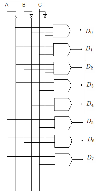
fig3. Logic Diagram of 3X8 Decoder
No comments:
Post a Comment